What is reverse conducting IGBT RC-IGBT?
Lgesemi: let's talk about reverse conducting IGBT (RC-IGBT). I have known about this device for a long time, but I feel that its application is limited, so I haven't delved into it further. Recently, I have been reading papers and found that Fuji has promoted and applied RC-IGBT as a key component in the field of electric vehicles in recent years. Therefore, I personally feel it is necessary to take some time to talk about this component. Perhaps RC-IGBT, like SiC MOSFE modules, also represents an important development direction in the field of electric vehicles
Reverse conducting IGBT, reverse conducting? Some friends may ask, isn't IGBT originally reverse conducting? Why is there such a term specifically coined. There may be a misconception here that IGBT is just a general term, because most industrial applications are inductive loads that require a diode chip to be anti parallel connected to the IGBT chip. Therefore, it is generally believed that IGBT must be reverse conducting. But strictly speaking, IGBT is IGBT, unlike MOSFET which has a body diode inside, and IGBT is an asymmetric device, which means that the forward and reverse voltage resistance is different. At this point, you may ask if there are asymmetric devices, then there must be symmetric ones. Yes, there are indeed. AB Rockwell's Power Flex7000 medium voltage current inverter uses Symmetric Gate Commutated Thyristor (SGCT), and the forward and reverse blocking voltages of SGCT are the same. Baliga's book "Fundamentals of Power Devices" also discusses symmetrical IGBTs in section 9.1. Interested readers can go and learn more about them
 Returning to our RC-IGBT, in simple terms, RC-IGBT combines IGBT and diode into one chip, as shown in the following figure:
 In order to appear more professional, Lao Geng feels it is necessary to explain the internal structure diagrams of IGBT, DIODE, and RC-IGBT. Some friends may not be familiar with such pictures yet, and they are not too complicated. Simply put, power devices are made by combining P-type and N-type semiconductors with different doping concentrations. The following figure shows the RC-IGBT image provided by Infineon. Lao Geng has added some annotations, and different colors represent different doping concentrations. The darker the color, the higher the doping concentration. The+symbol after the letter represents high doping concentration (heavy doping), and the - symbol represents low doping concentration (light doping).
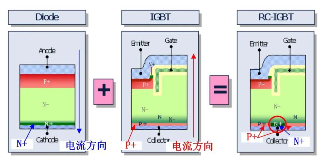
Given this level of understanding, it should still be acceptable to brag to people who don't understand the components. Let's first take a look at the FWD structure, which is composed of three layers of semiconductors: P+, N -, and N+. The diode with this structure is also called PiN diode, where i is the abbreviation of the English word Intrinsic, representing the intrinsic meaning, indicating that the doping concentration of the N-semiconductor in the middle is very low, similar to intrinsic. For a more detailed introduction to the PiN structure, please refer to Lao Geng's previous articles.
What is PiN diode?
Compared to FWD, IGBT is much more complex. The structure diagram of trench gate field terminated IGBT in the above figure consists of 5 layers of semiconductors with different doping concentrations, N+, P+, N -, N+, and P+, from top to bottom. If the two are combined and a portion of the P+layer at the bottom of the IGBT is reserved as N+, it becomes RC-IGBT. Now let's take a look at the more intuitive 3D structural diagram provided by Fuji.
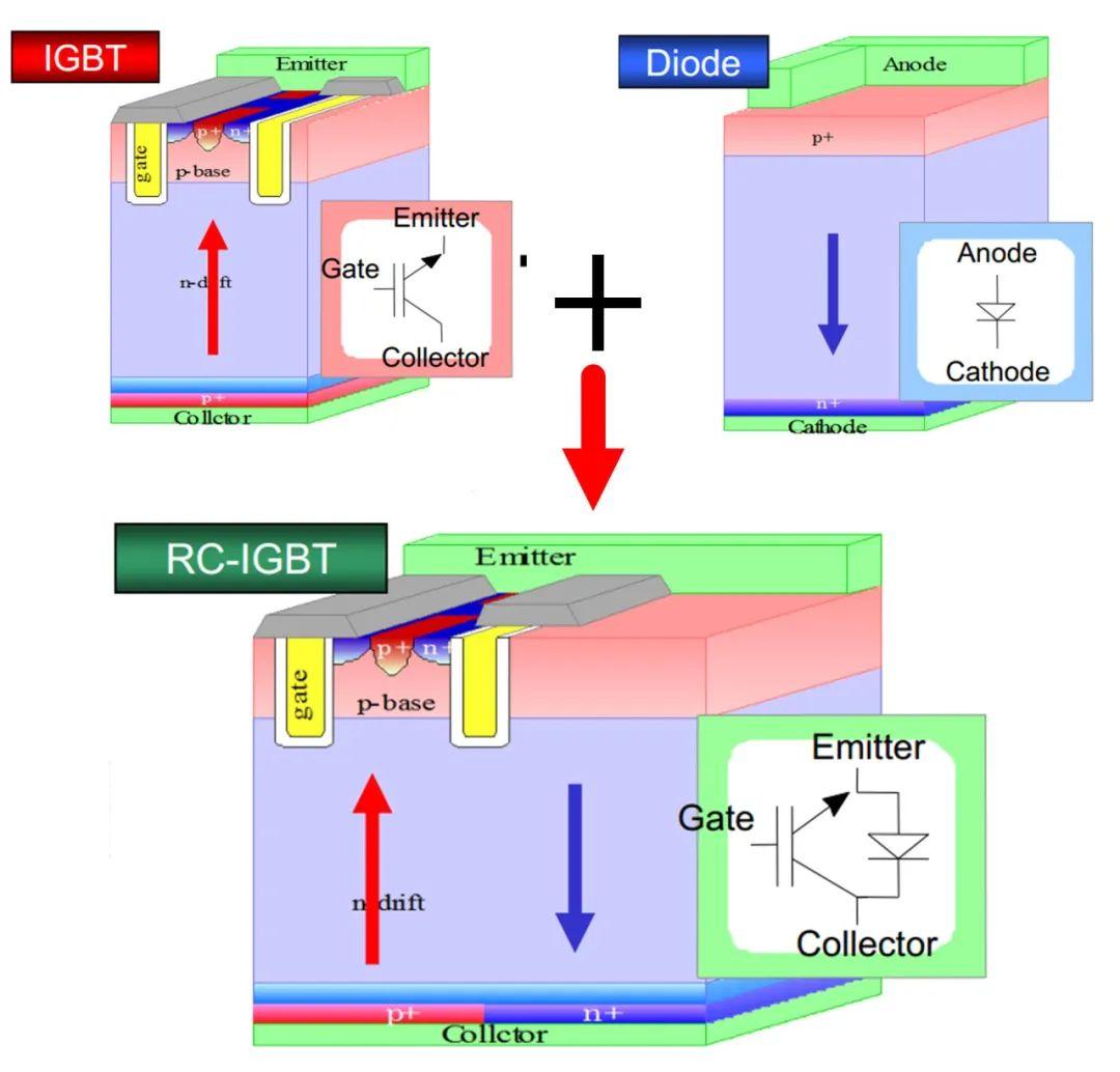
By now, I believe everyone should understand the difference between RC-IGBT and ordinary IGBT. Regarding the more in-depth working principle of RC-IGBT, Lao Geng will not introduce it. Now let's take a look at the advantages of RC-IGBT
Advantages of 03RC-IGBT
Advantage 1: Reduce chip size and lower costs
IGBT chips or FWD chips mainly include terminal regions and cell regions. When two devices are merged into one chip, the terminal portion can be shared, thus reducing the area of the terminal portion.
Normally, the area ratio of IGBT to FWD in traditional modules is about 2:1. RC-IGBT can save about 1/3 of the total chip area by integrating FWD inside the chip while keeping the area of traditional IGBT chips basically the same (slightly increased). At the same time, the number of chips is reduced, and the cost of soldering chips and bonding wires is also saved, which can significantly reduce the production and testing costs of chips. Similar to the figure below, a half bridge IGBT module requires 4 chips (2 IGBTs+2 FWDs), while using 2 RC IGBT chips is sufficient.
Advantage 2: Reduce thermal resistance
We all know that for ordinary IGBT modules, the specification sheet will separately provide the thermal resistance from the IGBT chip and diode chip to the substrate. For chips, the larger the area, the smaller the thermal resistance, which is more conducive to heat dissipation. As mentioned earlier, although RC IGBT can save the total chip area, it can increase the effective area of the diode by about twice, thus effectively reducing the thermal resistance of the diode and greatly improving its ability to withstand surge current (I2t tolerance). For IGBT, it can also reduce thermal resistance to a certain extent. The following figure shows the parameters given in a report released by Fuji. IGBT can reduce thermal resistance by 12%, and diode can reduce thermal resistance by 40%.
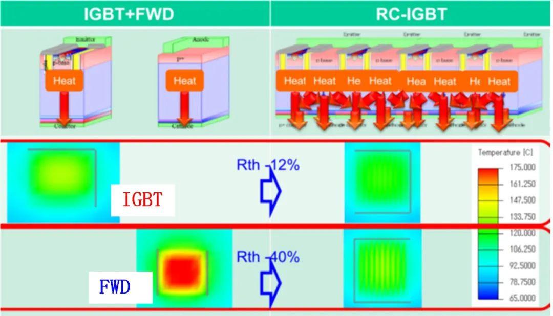
The smaller the thermal resistance, the more favorable it is for the device to dissipate heat. If the system only has IGBT chips or diode chips working, the junction temperature of the device will definitely decrease. However, when both IGBT and FWD are working, due to thermal interference between IGBT and FWD, the overall temperature may increase compared to traditional modules, as the losses of the two devices are on the same chip. Of course, this also depends on the switching characteristics of the RC-IGBT chip.
Advantage 3: Reduce junction temperature fluctuations
From the perspective of operating conditions, the improvement of RC-IGBT significantly enhances the power cycling capability of the device by addressing the issue of large junction temperature fluctuations caused by intermittent operation of IGBT and FWD chips in traditional modules. We all know that the lower the output frequency of the inverter, the more severe the IGBT junction temperature fluctuation, especially under locked rotor conditions. Due to the integration of IGBT and diode on the same chip, RC-IGBT generates a synthetic heat source through alternating operation, with consistent heat dissipation pathways, which can significantly reduce the junction temperature fluctuations of the chip and improve device reliability.
Seeing this, you may ask why RC-IGBT has not been widely applied yet, given its many advantages? Let's take another look at some of the issues that exist with RC-IGBT. The most common problem with RC-IGBT is the Snap back phenomenon in the forward output characteristics, as shown in the following figure [2]. In the initial stage of RC-IGBT conduction, the current density is very small and the VCE is large. However, when the VCE increases above a certain value, there will be a significant decrease in VCE, while the current density continues to increase, which is manifested as a negative resistance characteristic on the I-V curve. The Snap back phenomenon is not conducive to the parallel use of devices and can also affect power consumption under light load conditions,