Working principle of voltage regulator diode
Lgesemi: The characteristic of a voltage regulator diode is that after breakdown, the voltage at both ends remains basically unchanged. In this way, when the voltage regulator is connected to the circuit, if the voltage at each point in the circuit fluctuates due to fluctuations in the power supply voltage or other reasons, the voltage at both ends of the load will remain basically unchanged. Zener diodes are commonly represented by "ZD" followed by a number in circuits, for example, ZD5 represents the Zener diode numbered 5. Fault characteristics: The faults of the voltage regulator diode mainly manifest as open circuit, short circuit, and unstable voltage regulation value. Among these three types of faults, the former one shows an increase in power supply voltage; The latter two types of faults manifest as a decrease in power supply voltage to zero volts or unstable output. The models and voltage regulation values of commonly used voltage regulators are shown in the following table:
Model 1N4728 1N4729 1N4730 1N4732 1N4733 1N4734 1N4735 1N4744 1N4750 1N4751 1N4761
Voltage regulation value 3.3V 3.6V 3.9V 4.7V 5.1V 5.6V 6.2V 15V 27V 30V 75V
A voltage regulator is also a type of crystal diode that operates by utilizing the stable voltage characteristics of the breakdown region of a PN junction. Voltage regulators have been widely used in voltage stabilizing equipment and some electronic circuits. We refer to this type of diode as a voltage regulator to distinguish it from diodes used in rectification, detection, and other unidirectional conductive applications. The volt ampere characteristics and their symbols of the voltage regulator are illustrated in the diagram.
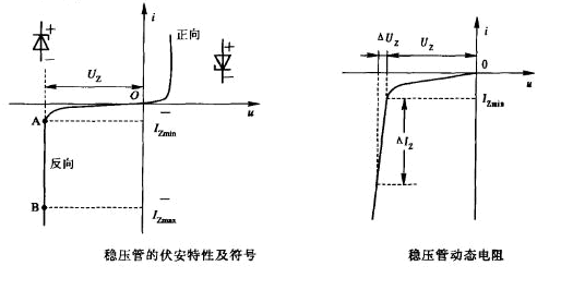
(1) The stable voltage Uz Uz is the breakdown voltage of the PN junction, which varies slightly with different operating currents and temperatures. For the same type of voltage regulator, there is a certain degree of variability in the voltage regulation value.
(2) The reference current value for the stable current Iz regulator during operation. It usually has a certain range, namely Izmin Izmax.
(3) The dynamic resistance rz is the ratio of the voltage change at both ends of the voltage regulator to the current change, as shown in the above figure, which varies with the working current. The larger the operating current, the smaller the dynamic resistance, and the better the voltage regulation performance.
(4) The voltage temperature coefficient is a coefficient used to indicate that the stable voltage value is affected by temperature changes. Different models of voltage regulators have different temperature coefficients for stable voltage, which can be positive or negative. A voltage regulator with a voltage stabilization value below 4V has a negative temperature coefficient for the stable voltage; The temperature coefficient of the stable voltage of a voltage regulator with a voltage stabilization value higher than 6V is positive; Between 4V and 6V, it may be positive or negative. In high demand situations, two pipes with opposite temperature coefficients can be connected in series for compensation (such as 2DW7).
(5) It has been pointed out before the rated power consumption Pz that the larger the operating current, the smaller the dynamic resistance, and the better the voltage regulation performance. However, the maximum operating current is limited by the rated power consumption Pz, and exceeding P2 will damage the voltage regulator. When choosing a voltage regulator, it should be noted that the current Iz flowing through the regulator should not be too large, Iz ≤ Izmax, otherwise it will exceed the allowable power consumption of the regulator. Iz should not be too small, Iz ≥ Izmin, otherwise the output voltage cannot be stabilized, which limits the range of changes in input voltage and load current.